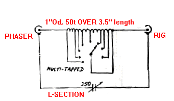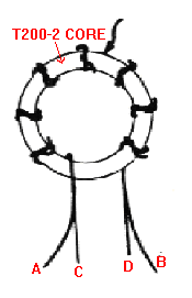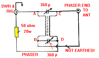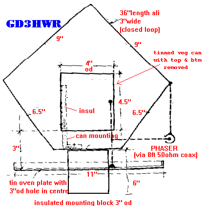


The mark 2 Crossfield Antenna was described in Sprat 76 by Alec, GD3HQR . He notes that although it showed no directivity at HF, it was possible to null out time base noise from a TV in an adjacent room. If a valve PA rig with the usual pi section o/p is used, the L-section may not be required. However, it is essential when used with transistor rigs having fixed tuned o/p filters. When tuning the loop, first approximately tune the L-match by adjusting for maximum RX noise. Then, with QRP, adjust C2 in small steps, at each step adjusting C1 and the L-netwprk for minimum SWR. When this is found, note the settings for future use. Repeat for other bands. Note C2 requires less capacitance at lower frequencies and more at higher frequencies. The author found that, with when properly adjusted, an SWR of at worst 1.5:1 was attained.
It was found that a 1m square sheet of metal - not earthed - placed under the wooden base improved high angle radiation for inter-G working on 3.5/7.0 Mhz.
Note that DC earth is connected to the coax used to connect the L-network to the phaser (it has a capacitive RF earth, which is all that is required).
The author found that his model, used indoors and only six feet above the floor, gave good results on 7 Mhz and above and was 'quite useful' on 3.5 Mhz. It even produced 'the odd QSO' on 1.8 Mhz.
Click to see a photograph of G3FCK's homebrew CFA (108 kilobytes)
(Please note: I have no personal experience of this system and cannot therefore offer any advice or further information. - Frank, G3YCC)