
By George Dobbs G3RJV
Experience has taught me that relatively few radio amateurs build complex equipment. Rather more of them are inclined to build small projects, which can be completed in an evening or a weekend, cost very little in parts, and will probably work first time. It is satisfying to go to bed knowing that you have built something with your own hands and it worked. Few of us get the chance to do that these days
Here are four simple projects, all of which could be built in a couple of hours or less. None of them is very original but all of them should work first time if built with care. Hopefully they all have practical applications for the QRPer.
I recall having a long conversation with the late Doug DeMaw, W1FB, who was an advocate for the use of the VXO in home built equipment. His contention was that the VXO is a very viable option for home built amateur radio equipment especially for miniature or portable stations. Some of the ideas below come from the scribblings I made at the time. What is offered here is a utility VXO circuit that can be used as a frequency source for a transmitter, or even a receiver, on a range of amateur bands.
The circuit for the VXO is a bipolar transistor oscillator followed by a bipolar tuned buffer stage. My prototype used 2N2222A transistors for both TR1 and TR2 but many similar types would work. I used 2N3904 devices in an earlier version. The oscillator has a stabilised supply derived from an 8.2 volt zener diode. I had intended to use a 9.1 volt zener but could not find one. Other constructors might like to use a three-pin voltage regulator chip of similar voltage.
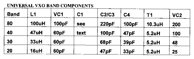
The oscillator is based on the popular Colpitts circuit. The capacitive feedback is via the capacitive divider provided by C2 and C3. These values vary according to band (see the band table). C1 is used to minimise the effects of the parallel capacitors, C2 and C3. Without C1, the upper frequency range of the oscillator would be restricted. By using an inductor, L1, and a variable capacitor, VC1, the crystal should pull slightly above its nominal frequency. The value of C1 will depend upon individual crystals. I found that around 100pF served very well for 40m. Try 100pF as a starter value on other bands and experiment.
Suggested values for L1 and VC1 are also given in the band values table. The suggested inductors are standard commercial moulded inductors. These values can offer considerable frequency shift. I make no numeric promises.
The oscillator stage is coupled to the buffer via C4, the value of which is ideally changed to suit the band. The table shows suitable values for C4. The buffer stage is tuned for the band in use using a tuned transformer, T1. These values for T1 and VC2 are chosen to resonate at the frequency of the crystal. The buffer amplifier operates in Class A to encourage a spectrally clean output.
Notes:
T1 for 40/30/20 - 5.2uH = 36 turns on T50-6 core. Link winding 10 turns
T1 for 80 -10.3uH=45 turns on T50-2 core. Link winding 12 turns
VC2 is a trimmer capacity Value given is theoretical capacitance to resonate T1 on the QRP calling frequency for the band in question
VC1 may be a mix of fixed and variable capacitance. The values for T1 and VC2 can be taken from the band table. To save additional calculations, I used the same value of inductance for all the bands from 40 to20m. For 80m L1 is a larger inductance tuned with a larger capacitor. The figures in the table show the calculated values for VC2 to hit the International QRP Calling Frequencies on the 4 bands. These are 3.506MHz, 7.030MHz and 14.060MHz and 14.060MHz
The higher frequency version of T1 (40, 30 and 20m) can be made using about 60cm of 26swg (about 25 awg) enamelled copper wire wound to occupy about three-quarters of the core. The version of T1 for 80m will need 32swg (about 29 awg) enamelled copper wire.
T1 and VC2 should peak the output of the VXO at the desired frequency. This resonance ought to be fairly flat over the whole range of the VXO. If this is not so, the bandwidth of the tuned circuit can be increased by damping it with a resistor. Connect a resistor, try 4.7K or perhaps 10K, across the tuned winding of T1.
K.P.S.Kang, VU20WF of the recently formed VU QRP Club has designed several club projects based upon very small printed circuit boards. The first of these that I saw and built was transmitter based on the W6BOY Pixie. My version is much bigger than the original - for ease of building.
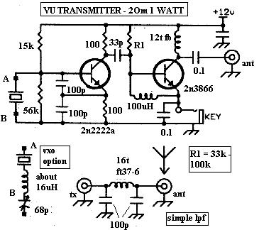
The drawing shows the circuit of the VU Transmitter. T1 is a Colpitts oscillator with C1 and C2 forming the capacitive feedback divider. The oscillator is crystal controlled but VC provides some useful frequency shift. VC can be a small variable capacitor or a trimmer. The maximum capacitance should be in the 50 to 75pF range. Larger values offer more shift but attempting to move the frequency too much will produce instability and eventually the oscillation will cease. The addition of an inductor of about 16uH will offer several kHz of frequency shift. (see VXO Option)
C3 couples the signal to the power amplifier, T2. The biasing resistor R5 controls the output of T2. Usually a value in the range 33K to 100K is suitable. The higher the value - the higher the output of T2. 47K is a useful starting value for experimentation. I suggest that T2 is not run higher than 1 watt of RF output power. It will get warm and a small star heatsink ought to be fitted.
The collector load for T2, RFC1, is a home made RF Choke. Carefully wind 12 turns of 38 swg (about 34 awg) enamelled copper wire (any small enough gauge will do) through a ferrite bead. RFC2 is a small 100uH axial choke which is essential when using T2 as the receiver mixer. It also provides a useful RF load on the input of T2 and increases the drive to T2. The transmitter output is coupled from the collector of T2 via C4 to a low pass filter.
It occurred to me that it might be useful to have a small general purpose active aerial for times when I might have a receiver and be without an aerial. The requirements seem to be for a small whip antenna, or similar, to feed a radio frequency amplifier capable of around 20 to 30 dB of gain. To much gain and local noise or even internal amplifier noise becomes a problem and too little gain and it will serve little purpose. The short antenna will offer a high input impedance and the output will probably need to be low impedance to suit most receiver inputs.
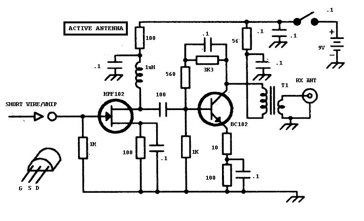
The Active Antenna is a two-stage amplifier using a FET followed by a bipolar transistor. The FET stage offers a high impedance to the small antenna.
I chose not to use the usual telescopic whip but mounted a socket for a short wire antenna. Apart from saving the cost of a telescopic whip, this has several advantages. The length of wire can be varied according to the desired amount of signal pick up, the wire can be moved around for best reception and the unit is smaller.
TR1 is an MPF102 but the common 2N3819 would do the job. Be careful about the pin placement, they are not the same. TR1 is biased by choice of the source resistor and a 1mH RF Choke provides a RF load at the drain. Although no large signals are involved here, it is wise practice with these FET RF amplifiers to keep the input physically away from the output.
The bipolar RF amplifier, TR2, uses shunt feedback between the base and collector and the un-bypassed emitter resistor also provides some degenerative feedback. Most common transistors will serve for TR1 although it should have a fairly high fT.
A small RF Transformer matches the output of TR2 to the typically low impedance found in receiver input circuits. I opted for a very simple choice, a transformer wound on a small "pig nose" ferrite former - they are common items in the surplus market.
Fig2. shows the winding of the transformer. The primary is 12 turns of 30 swg (about 28 awg) enamelled copper wire and the secondary is 2 turns wound from the opposite end.
Fig.2. also shows how the connections are made to the transformer. More sophisticated constructors might like to make a trifilar wound 4:1 RF transformer but the simple arrangement I used appears to work well.

This simple little circuit appears to be at home with a variety of receivers and it a useful extra item to have for casual listening with resort to a larger antenna.
When operating a receiver, there is something re-assuring about have a little meter needle dancing up and down in sympathy with the signal strength. The fact that it may not be doing much in the way of objective measurement seems to be of little importance. The more experienced operator knows what an S7 signal sounds like on the receiver and also tends to doubt anyone who says "you are S7 on the meter". Many S-Meters only offer subjective readings but they do look nice on the front panel.
So I begin this little project with honesty. The meter described here has no objective accuracy at all, but it does indicate the relative audio output of the signal being tuned. Its chief advantage is cosmetic - it makes the front panel look better and gives the pleasing effect of seeing the signal as well as hearing it. It is based on a circuit by HE9VXB
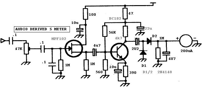
Since the circuit has to connect to the existing receiver audio stages, it is important that it does not offer a significant load to these circuits on the point of contact. Thus the input stage for the S-Meter offers a high impedance. A relatively high value pre-set potentiometer feeds the signal to a FET stage. This arrangement is unlikely to have much effect wherever it is connected, apart from sampling the audio signal. The stage really acts as an impedance transformer.
The capacitor, C4, couples the audio signal to a relatively high gain audio amplifier stage. This uses a bipolar device. Once again this could be almost any generic NPN transistor. I have a stock of the BC182 so that is what I used. If, in practice, the overall gain of the S-Meter seems a little low, try increasing R4 to around 100K ohms.
The capacitor, C6, feeds the audio signal to a detector circuit which converts the audio signal into a relative DC signal. D1 and D2 act as a voltage doubler detector to drive the meter from the load, R9. The diode types are also uncritical. Mine are the popular 1N914, or they may have been the 1N4148 - who knows!
C8, a 4u7 capacitor, smoothes out the movement of the voltage. This may need a little experimentation. If you want the needle to give steady readings, increase the value of C8, if you like it to dance around a little, decrease C8. I found that 4u7 was a good compromise value.
The meter is one of those small edge-wise CB type S-Meters so often found at reasonable prices. They usually have a full-scale deflection of some 200uA. Any meter with a similar full-scale deflection would do the job.
The question remains - where to connect the S-Meter? I tried the circuit on several receivers, from simple direct conversion receivers to commercial superhets.. The most appropriate place seems to be at the top end of the audio gain control. Not the slider of the control as this would obviously change the reading as the audio gain control was used. In most cases this will give enough audio signal to produce a useful range of readings. However it is possible to connect the input of the meter further down the audio amplification circuitry. There is no reason why it cannot be connected directly on to the output at the loudspeaker or headphone socket. The only answer is to try it and brighten up the front panel of that simple receiver.
Price (UK) Ł16.00 inc postage - Ł17.00 for Europe. Orders to the G QRP Club,
Mr FW Lee, G3YCC, 8 Westland Road, Kirk Ella, Hull. HU10 7PJ.
Cheques to G QRP Club.
Some kits are available from Bill Kelsey, N8ET kanga@bright.net
My thanks to George, G3RJV for giving me permission to include these projects, which appeared in Sprat 100
Frank, G3YCC